Oscillator Circuits: RC, LC, Wien Bridge, and Crystal
An oscillator converts DC power into a repeating signal. Some oscillators make sine waves for measurement and communication; others make clock or timing signals for digital systems. The right oscillator depends on waveform, frequency, stability, distortion, cost, and tuning range.
Learning Objectives
By the end of this lesson, you should be able to explain the Barkhausen criterion, calculate Wien bridge and LC resonant frequency, compare RC, LC, crystal, and relaxation oscillators, and identify practical stability and layout checks.
Oscillation Conditions
For a linear feedback oscillator to sustain a sine wave at one frequency, the loop must satisfy the Barkhausen criterion:
$$
A\beta = 1 \angle 0^\circ
$$
where A is amplifier gain and beta is feedback factor. At the oscillation frequency:
- loop phase shift is
0 degor360 deg; - loop gain is exactly
1after startup; - loop gain is slightly above
1at startup so noise grows into an output signal; - amplitude control reduces gain to avoid clipping.
If loop gain stays too high, the waveform distorts. If loop gain falls below 1, oscillation dies.
Oscillator Families
- RC oscillators: audio and low-frequency sine waves; easy tuning, modest stability.
- LC oscillators: RF sine waves; higher Q and better high-frequency behavior.
- Crystal oscillators: precise clock frequencies; excellent stability.
- Relaxation oscillators: square, ramp, or triangle waveforms; simple and flexible, not low-distortion sine sources.
Wien Bridge Oscillator
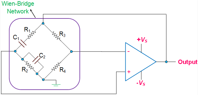
The Wien bridge oscillator uses an op-amp and a lead-lag RC network. For equal R values and equal C values:
$$
f_0 = \frac{1}{2\pi RC}
$$
At f0, the RC network has zero phase shift and feedback factor 1/3, so the non-inverting amplifier gain must settle at:
$$
A_v = 3
$$
For a non-inverting amplifier:
$$
A_v = 1 + \frac{R_f}{R_g}
$$
So a nominal Wien bridge oscillator uses Rf = 2Rg.
Worked Example: 1 kHz Sine Source
Choose C = 100 nF.
$$
R = \frac{1}{2\pi f_0 C}
= \frac{1}{2\pi \times 1000 \times 100 \times 10^{-9}}
= 1.59 k\Omega
$$
Use 1.6 kOhm for both RC resistors. For gain, choose Rg = 10 kOhm and Rf = 20 kOhm, then add amplitude stabilization.
Amplitude Stabilization

The oscillator must start with loop gain slightly greater than 1, then reduce gain as amplitude grows. Common methods are:
- back-to-back diodes in the gain path: simple but adds distortion;
- small lamp or thermistor: low distortion but slower and less common;
- JFET or optocoupler automatic gain control: better for instruments.
LC Oscillators
At RF frequencies, LC tanks are preferred because high-Q inductors and capacitors can store energy efficiently.
The ideal resonant frequency is:
$$
f_0 = \frac{1}{2\pi\sqrt{LC}}
$$
Real inductors have series resistance and parasitic capacitance, so measured frequency and Q differ from ideal calculations.
Try It: LC Resonance Calculator
Enter any two values and leave the third empty.
Formula: `f0 = 1 / (2 pi sqrt(LC))`.
Colpitts Oscillator
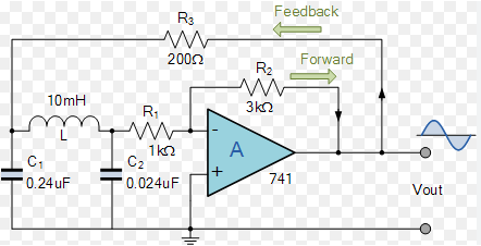
A Colpitts oscillator uses a capacitive divider for feedback. If C1 and C2 are in series across the tank, the effective capacitance is:
$$
C_{eq} = \frac{C_1C_2}{C_1 + C_2}
$$
Then:
$$
f_0 = \frac{1}{2\pi\sqrt{LC_{eq}}}
$$
Colpitts circuits are common in RF because capacitor ratios are easier to control than tapped inductors.
Hartley Oscillator
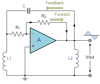
A Hartley oscillator uses an inductive divider. In the simple ideal case:
$$
f_0 = \frac{1}{2\pi\sqrt{(L_1 + L_2)C}}
$$
If the inductors are coupled, mutual inductance changes the effective inductance, so practical designs must account for the physical coil.
Crystal Oscillators
Quartz crystals behave like very high-Q resonators. They provide far better frequency stability than ordinary RC or LC parts.
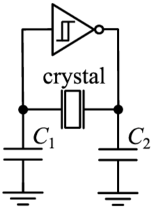
The Pierce oscillator is common in microcontrollers:
- crystal between inverter input and output;
- feedback resistor biases the inverter in its linear region;
- two load capacitors to ground;
- short traces and a quiet local ground.
The load capacitor value is not arbitrary. For two equal capacitors:
$$
C_L \approx \frac{C_1C_2}{C_1 + C_2} + C_{stray}
$$
If C1 = C2 = 22 pF and stray capacitance is about 3 pF, the crystal sees roughly 14 pF.
Relaxation Oscillators
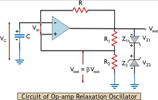
A relaxation oscillator uses a comparator or Schmitt trigger with an RC ramp. The capacitor charges until an upper threshold is reached, then discharges until a lower threshold is reached.
title "Relaxation oscillator concept"
time start=0 end=6 unit=ms divisions=6
OUT: square label="Comparator output" low=0 high=5 duty=50 cycles=3 unit=V color=#2563eb
RAMP: triangle label="Timing capacitor" min=1.5 max=3.5 cycles=3 unit=V color=#16a34a
marker H at=1 label="upper threshold"
marker L at=2 label="lower threshold"
Relaxation oscillators are excellent for square and triangle waves, but their frequency is less precise than crystal clocks and their sine wave distortion is high unless extra shaping is added.
Performance Metrics
- Frequency stability: change with temperature, supply, load, and aging.
- Phase noise and jitter: short-term timing uncertainty.
- Harmonic distortion: unwanted frequency components in sine outputs.
- Startup margin: ability to start reliably at temperature and supply extremes.
- Load pulling: frequency shift caused by load changes.
Approximate stability ranking:
- RC oscillator: lowest stability, flexible and cheap.
- LC oscillator: moderate stability, useful for RF tuning.
- Crystal oscillator: high stability, best for clocks.
- TCXO/OCXO: temperature-compensated or oven-controlled crystal oscillator for precision systems.
Practical Design Checks
- For Wien bridge circuits, include amplitude stabilization.
- For LC circuits, keep tank wiring short and use high-Q parts.
- For RF circuits, include buffering so the load does not pull the oscillator.
- For crystals, match load capacitance to the datasheet and avoid long traces.
- For digital clocks, check startup time, drive level, and PCB contamination around high-impedance nodes.
- For any oscillator, measure actual frequency, amplitude, and waveform shape.
Common Mistakes
- Setting Wien bridge gain exactly to
3with no startup margin. - Letting amplitude clip and calling the result a sine wave.
- Ignoring stray capacitance in LC and crystal circuits.
- Loading the resonant tank directly.
- Using random load capacitors on a crystal.
- Placing a crystal next to fast switching traces.
Summary
Oscillators need loop gain, correct phase, a frequency-selective network, and amplitude control. Wien bridge oscillators are useful for audio sine waves, LC oscillators for RF, crystals for precise clocks, and relaxation oscillators for square or ramp signals. The formulas are simple starting points; stability, loading, parasitics, startup, and layout decide whether the oscillator works reliably.
Further Reading
- Analog Devices, "MT-086: Fundamentals of Phase Locked Loops and Oscillators."
- Texas Instruments, "AN-263 Sine Wave Generation Techniques."
- Microchip, "Crystal Oscillator Basics and Crystal Selection."
- Horowitz and Hill, The Art of Electronics, oscillator chapters.